
Even the best machine cannot deliver its full performance without proper operation and maintenance. AS-series self loading mixer is designed to load, weigh, mix, transport, and discharge concrete efficiently on small to medium construction sites in Indonesia. To help operators get the most out of the machine, this self loading concrete mixer user manual provides clear guidance on installation, calibration, daily operation, maintenance, common faults, and emergency handling, serving as a practical reference before and during use.

Self Loading Concrete Mixer – Arrival & Assembly Guide
How to Assemble Self Loading Mixer Truck? In Indonesia, our self loading concrete mixers are usually available as ready-to-use machines. However, for customized configurations or partial disassembly during transport, our local service team provides on-site assembly. The following guide shows detailed assembly steps and practical tips for operators.
Assemble the Cabin
Remove cabin support frame and slowly lower the cabin onto chassis.
Secure the cabin and ensure it is properly aligned.
Tip: Handle with care to avoid tilting or damaging parts.
Install the Right Headlight
Place the right headlight into the reserved slot.
Tighten bolts and ensure the light direction is correct.
Adjust beam angle if necessary for safe nighttime operation.
Install the Wheels
Use a jack to lift the vehicle, providing enough space for wheel installation.
Use a 27–30 mm socket wrench to tighten all lug nuts evenly.
Check that each nut is secure to ensure wheel balance and stability.
Rotate the Drum Support Frame
Rotate the drum support frame to align parallel with the chassis.
Ensure it is fixed securely for the drum installation.
Install Cabin Footboard
Mount the footboards on both sides of the cabin.
Tighten screws to ensure safe access for operators.
Install Mudguards
Position mudguards above the wheels.
Tighten bolts and check for clearance between tires and mudguards.
Tip: Ensure tires rotate freely without rubbing against the mudguards.
Lift and Fix the Drum & Gearbox
Use lifting equipment to place the concrete drum.
Align the drum with the gearbox and secure it with bolts.
Ensure the gearbox is tightly fixed to prevent vibration-related loosening.
Connect Gearbox Oil Pipes
Connect oil pipes from gearbox motor to the corresponding ports.
Check for tight and leak-free connections.
Tip: Add a small amount of lubricating oil for a test run.
Install Discharge Chute Support
Mount the discharge chute support to the reserved position.
Tighten bolts to ensure stability during unloading.
Tip: Check load balance during discharge.
Lift Cabin & Secure Bolts
Use lifting equipment to place the cabin onto the chassis.
Secure the cabin with four bottom bolts.
Ensure the cabin is stable and does not sway during operation.
Install Cabin Guard & Wires
Install the bottom guard to protect the cabin underside.
Connect cabin wires, monitor lines, and weighing system cables.
Tip: Ensure all wires are properly connected to avoid malfunctions.
Install the Loading Bucket
Mount the loading bucket to the designated position.
Ensure the bucket is securely connected to the mixing system.
Tip: Test lifting and lowering to confirm smooth operation.
With the self loading mixer fully assembled, it’s time to set up the weighing system. Proper calibration ensures accurate batching and smooth operation on Indonesian construction sites. The next section will guide you through the key steps for reliable performance.
Setting Up an Accurate Weighing System for Your Self Loading Mixer
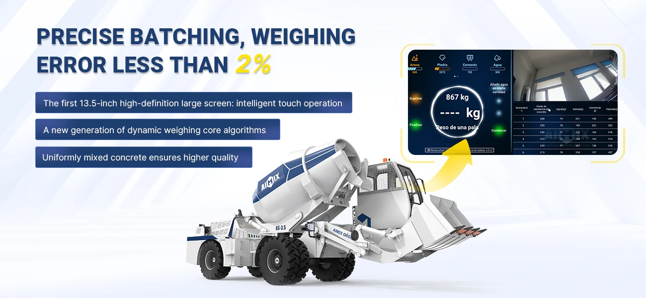
Featuring our cylinder-based measurement technology and next-generation dynamic weighing algorithm (accuracy error ≤2%), the weighing system is a core advantage of the AS-series Self Loading Concrete Mixers. Proper setup ensures each batch achieves consistent, high-precision results—critical for reliable concrete quality on Indonesian construction sites.

Main Interface Overview
The weighing interface allows operators to set mix volume, select formulas, monitor weighing in real time, and manage records.
Set Target Concrete Volume / Weight
Click the task setting area to set the target mix volume and formula for each batch. Enter the desired concrete output.
Example: For a 3.5 m³ self loading mixer, enter 3.0 m³ first, then adjust according to actual loading conditions.
Choose a formula from the common recipe list or add a new one as needed.
After confirming, click Save in the upper-right corner.
Recipe Settings
To create or edit formulas:
Settings → Edit Formula → Formula Management
Add recipe steps based on your required mix design.


Feeding & Material Weighing
Tare the bucket
After setting the concrete target and formula, lift the empty bucket.
If the displayed value is not zero, click “Tare On/Off”.
Once the screen shows 0, the tare is successful.
Select material type
Before shoveling materials, select the corresponding material icon.
The icon will turn yellow, indicating active weighing for that material.
Lift the boom and unload into the drum—weight will automatically accumulate under that material (e.g., “Sand”).
If Target Weight Is Exceeded
If the current bucket weight exceeds the preset target, the system will issue a reminder.
Keep the boom lifted, click “Clear”, then lower the bucket.
Dump part of the material and lift again until the weight meets the target.
To delete any previous weighing result:
Settings → Work Record Management → View Record → swipe left to delete


Water Supply Settings
Operators can choose automatic or manual water supply.
Automatic Water Supply Options
Add water by quantity
Add water by timing
Click Start to begin automatic filling.
Adjust with [+] or [-] based on real site conditions.
Weighing Record Printing
After collecting weighing data, click Print to output the complete weighing record for documentation and project tracking.
With the weighing system properly calibrated, your self loading concrete mixer is now ready for daily operation. The next step is knowing how to run the machine safely and efficiently—from loading and mixing to driving and discharging—so every batch on your Indonesian jobsite is produced smoothly and consistently.
How to Operate a Self Loading Concrete Mixer?
Operating a self-loading concrete mixer requires attention to safety, correct activation of each system, and coordinated handling of the loader, drum, and driving controls. The following step-by-step guide offers a practical workflow suitable for daily use on Indonesian job sites.
Pre-Operation Safety Checks
Before starting the machine, conduct a full walk-around inspection to avoid system faults or safety risks.
- Fuel & Engine Oil – Confirm fuel volume is sufficient for the entire batching cycle; check oil level and ensure no leakage around pipes or connectors.
- Hydraulic & Oil Lines – Look for loose fittings, cracks, or dripping areas, as hydraulic pressure is essential for lifting and mixing.
- Tire Pressure – Verify all tires are inflated evenly to avoid instability on uneven construction roads.
- Surroundings – Clear away debris, loose stones, or materials obstructing the travel path or loader bucket.
- Cab Access – Ensure steps, handrails, and the cab floor are dry and safe for entry.
Start-Up Procedure
Once the surrounding area is confirmed safe, get into the cab and follow the proper start-up sequence.
- Ignition – Sit firmly in the seat, adjust your view, and turn the key to start the engine.
- Instrument Check – Inspect indicators such as oil temperature, engine speed, hydraulic pressure, and fuel gauge to ensure they read normally.
- Air Brake System – Confirm air pressure reaches 8 bar (0.8 MPa) before moving; low pressure means braking is unsafe.
- Activate Weighing System – Press and hold the hydraulic weighing system switch for 3–5 seconds. The system will self-check and enter standby mode.
Loader Bucket Operation
The loader bucket handles raw materials such as sand, gravel, and aggregates. Smooth operation improves productivity and prevents spillage.
- Withdraw Bucket – Retract the bucket fully to prepare for scooping material.
- Tipping Bucket – Tilt forward to dump excess material or adjust the loading angle.
- Bucket Open / Close – Control the bucket’s grasping capacity depending on material hardness and bulk.
Important Safety Note:✔ The piston rod must be fully retracted before raising the bucket to its maximum height; otherwise, hydraulic pressure may overload the system.
Boom & Drum Rotation Controls
The boom and drum rotation allow precise material handling and discharge positioning.
Drum Operation
The mixer drum is the heart of the machine, responsible for producing uniform, high-quality concrete.
- Drum Up / Down – Adjust the drum angle for mixing efficiency or smoother discharge.
- Mixing Mode – Engage the mixing switch after all materials are loaded; the drum rotates at the optimal speed to blend aggregates, cement, and water.
- Discharge Mode – Reverse the drum rotation and adjust the height and angle to discharge concrete precisely without spilling.
Driving & Mobility Controls
Self-loading mixers combine transportation, mixing, and loading functions, so stable driving is essential for safety and productivity.
- Forward / Backward – Select the appropriate travel direction with the shuttle lever.
- Initial Gear – Use neutral or initial gear when transitioning from mixing to driving.
- Working Speed – Maximum 25 km/h, suitable for job site movement and material transfer.
- Low-Speed Mode – Minimum 8 km/h for tight spaces or heavy-load driving.
- Road Speed (No-load) – Up to 38–40 km/h only on flat, approved roads when relocating machines.
- Left Gear Lever – Controls low/high working speeds for construction zones.
- Right Gear Lever – Controls road gears for longer travel.
- Gas Pedal – Adjusts speed; apply steadily to avoid jerky motion.
- Brake Pedal – Main braking function; test responsiveness before each shift.
- Handbrake – Always engage when parked or loading to prevent sliding.
Auxiliary & Daily Operation Functions
These supporting features help ensure continuous operation and machine cleanliness.
- Hand Accelerator – Lock the engine at a stable RPM during mixing, loading, or hydraulic actions.
- High-Pressure Water Gun – Used to clean the drum, chute, bucket, and machine body after each shift to prevent concrete buildup.
- Add Water System – Controls accurate water dosing for concrete mix designs.
- Front Window Glass Switch – Improves ventilation and driver comfort in hot Indonesian climates.
Maintenance Guide for Self Loading Concrete Mixer
Regular maintenance is essential to ensure stable performance, extend machine lifespan, and avoid downtime on Indonesian job sites. The following guide summarizes the daily, periodic, and major service items for your self loading concrete mixer.
| Self Loading Concrete Mixer Truck Maintenance Cycle | |||||||||
|---|---|---|---|---|---|---|---|---|---|
| SN | Maintenance Item | Quantity | Maintenance Content | Interval Time (Hour) | |||||
| 10 | 50 | 100 | 300 | 600 | 1000 | ||||
| 1 | Heat sink | 25L | Coolant | Check | Replace | ||||
| 2 | Engine oil | 13.6L (Fill to 2/3 of the oil level gauge) | Engine oil CC30/CC40 | Check | Replace | ||||
| 3 | Fuel tank | 120L | Fuel HO/#-10 | Check | |||||
| 4 | Engine oil filter | 1or 2 | Filter element | Replace | |||||
| 5 | Fuel filter | 1 | Filter element | Replace | |||||
| 6 | Air filter | 1 | Filter element | Replace | |||||
| 7 | Hydraulic tank | 120L(Fill to 2/3 of the oil level gauge) | Hydraulic oil#46/#64/#68 | Check | Replace | ||||
| 8 | Hydraulic oil return filter | 1 | Filter element | Replace | |||||
| 9 | Hydraulic oil inlet filter | 1 | Filter element | Replace | |||||
| 10 | Hydraulic oil low pressure filter element | 1 | Filter element | Replace | |||||
| 11 | Hydraulic oil high pressure filter element | 1 | Filter element | Replace | |||||
| 12 | Gearbox | 21L (Fill to 2/3 of the oil level gauge) | Transmission oil SAE80W-85/80W-90 | Replace | |||||
| 13 | Drive axle | 6L | Heavy duty gear oil | Replace | |||||
| 14 | brake pump | 0.5L | Brake Fluid #912 or DOT3 | Replace | |||||
| 15 | Gearbox | 6L(Fill to 2/3 of the oil level gauge) | Heavy duty gear oil | Replace | |||||
| 16 | Cylinder pin | 1 | Lubricating oil 400 lithium base grease | Lubricating oil | |||||
| 17 | Roller | 1 | Lubricating oil #00 lithium base grease | Lubricating oil | |||||
| 18 | Slewing mechanism | 1 | Lubricating oil #00 lithium base grease | Lubricating oil | |||||
| 19 | Frame articulation | 1 | Lubricating oil #00 lithium base grease | Lubricating oil | |||||
| 20 | Transmission shaft | 1 | Lubricating oil #00 lithium base grease | Lubricating oil | |||||
| 21 | Water separator | 1 | Drying tank | Remove water | Replace | ||||

Daily & Routine Maintenance
Lubrication
Apply grease to the boom and bucket pins once per shift.
Fully-sealed slewing ring: grease every 15 days.
Support rollers: grease every shift; keep the track continuously lubricated.
Other lubrication points: grease every 2–3 days.
Fluids & Levels
Check hydraulic oil level; refill if low. Check gearbox oil level; top up if needed.
Water tank: fill with antifreeze suitable for local temperatures.
After daily operation, wash the mixer to prevent material buildup.
Air System
Clean the air filter every 1–2 days; replace immediately if damaged.
Inspect air filter hoses for wear and replace if necessary.
Engine Checks: Before operation, check engine oil and coolant levels.
First Service (50–100 hours)
After the first 50–100 hours of use:
Engine Oil Change; Drain old engine oil completely and replace the oil filter.
Add approx. 12 L diesel engine oil: Summer: CC40; Winter: CC30
Bolt Retightening Check and tighten:
Gearbox mounting bolts
Engine mounting bolts
Drum-to-frame bolts
Drive shaft bolts
Hydraulic pump mounting bolts
Radiator base bolts
Torque Converter Oil Change
Drain dirty oil and flush with new oil.
Replace the inlet oil filter.
Refill approx. 20 L No. 8 hydraulic transmission oil.


200-Hour Maintenance Service
At 200 working hours:
Fully drain hydraulic oil, flush with clean oil.
Replace the hydraulic filter.
Refill approx. 100 L hydraulic oil.
After this, replace every 500 hours or every 6 months, with pipeline flushing.
One-Month Service
Within one month of initial use:
Replace main axle gear oil and wheel reduction gear oil.
Add 18# hypoid gear oil:
Main axle: 4 L
Each wheel reduction: 2.5 L
Monthly Inspection (200 Hours or 1 Month)
Grease the drive shaft and universal joint until grease seeps out. Retighten:
Gearbox mounting bolts
Gearbox-to-drum bolts
Drum-to-frame bolts
Drive shaft bolts
Hydraulic pump bolts
Radiator base bolts
Wheel lug nuts
500-Hour or Seasonal Service
Every 500 hours or every 6 months:
Perform all 200-hour maintenance items.
Replace hydraulic oil and all related filters.
Drain, flush, and refill the hydraulic oil tank with clean oil.
For Complete Maintenance Details

Regular maintenance reduces the risk of failure, but unexpected issues can still occur on site. When routine checks are not enough, quick and proper emergency handling becomes essential. The next section explains how to deal with common malfunctions safely and effectively.
Emergency Measures for Malfunctions of Self Loading Concrete Mixer
On construction sites, self-loading concrete mixer machines may occasionally encounter unexpected issues. To help your team identify problems quickly and restore operation as soon as possible, this chapter organizes common malfunctions into simple, easy-to-follow steps—making troubleshooting clearer and safer.
Drum Not Rotating
When the drum does not respond, or cannot rotate forward or reverse, check the following items:
Hydraulic Oil Level and Oil Quality Check
Oil that appears dark, milky, or contaminated indicates deterioration → Drain and replace the hydraulic oil completely
Oil Inlet Ball Valve Status
Hydraulic Filter Condition
Check the Control Cable and Control Mechanism
Normal synchronous movement → Continue to step (5)
Abnormal or no movement, investigate the following:
Loose or incorrect connection between control lever and cable
Cable fixation issues
Broken cable (no push–pull response) → Replace cable
Faulty controller → Replace controller
If the rear controller is malfunctioning, temporarily operate using the cabin controller
If both controllers are unavailable, carefully actuate the pump control valve lever manually (small angle only) to complete emergency discharge
⚠️ Large-angle manual operation may cause sudden high-speed rotation and must be avoided.
Pump Control Valve Function
Drum responds normally → Proceed to step (6)
No response indicates possible issues such as:
Loose connection between valve shaft and lever
Internal linkage damage
Contaminated control oil passages → Clean using compressed air
Jammed valve spool → Replace the control valve assembly
Check Charge Pump Pressure
Insufficient pressure suggests a faulty high-pressure relief valve → Replace
Zero pressure indicates damage to pump input shaft or spline → Replace
Fluctuating pressure often results from a blocked filter
Drum Rotates in Only One Direction

Controller and Cable Travel
Move the control lever to full stroke and observe the pump control valve angle:
Correct angle without drum movement → Proceed to step (2)
Unequal or limited movement suggests cable or controller issues:
Measure cable travel in both directions
One-direction-only movement → Cable damage
Normal cable travel → Controller requires recalibration to balance forward and reverse stroke
Control Valve Linkage Integrity
After disconnecting the cable joint, inspect the following components:
Input shaft wear
Internal linkage damage
Blocked control oil passages caused by contaminated oil
Obstructed servo control ports on the pump body
Check Charge Pump Check Valve
Contamination → Clean using clean hydraulic oil
Mechanical damage → Replace the check valve
Directional Relief Valve and Shuttle Valve
If no high pressure in that direction → Remove safety valve to clean or replace
Check shuttle valve spring—broken → Replace or add spacer
Note: Steps 3.2.3–3.2.4 should be performed by technicians with hydraulic experience.

Slow System Response

PTO speed: must maintain 500–600 RPM
Hydraulic oil level/quality: refill or replace
Hydraulic filter vacuum gauge: if > -2.5 PSI → Replace filter
Charge pump pressure
Motor return-line back-pressure valve
Pump control valve & linkage
Hydraulic System Overheating
(1) Low oil level / poor oil quality → Refill or replace
(2) Oil inlet valve closed → Open
(3) Filter clogged → Replace
(4) Check cooling fan operation, If fan does not rotate → Continue to step (5)
(5) Temperature Control Circuit
When the cooling fan does not operate:
Inspect the 15A fuse, Verify wiring connections, Confirm manual/automatic switch functionality, Test temperature switch in water ≥60 °C → Fan should activate
In case of temperature switch failure, manual mode may be used temporarily for forced cooling.
(6) Charge Pressure and Motor Case Pressure
Standard operating pressure: approx. 18 bar; Lower readings indicate wear in charge pump or faulty back-pressure valve → Replace as required

Emergency Plan for Severe Failures
In the event of engine, hydraulic pump, motor, or gearbox failure where drum rotation is completely impossible, emergency discharge must be performed immediately to prevent concrete solidification.

Plan A: Discharge Through Drum Service Ports
Suitable for engine failure and other no-power conditions.
Remove the two rear service port covers
Open the service ports
Loosen the two high-pressure hoses on the hydraulic motor
Concrete will discharge quickly from the service ports
⚠️ Warnings:
High-pressure hot oil may spray when hoses are loosened; ensure proper protection
Drum may rotate from inertia; use wooden blocks to lock the rollers before operation
Plan B: Hydraulic Rescue Using Another Mixer
(1) Preparation
Rescue hoses: 2 high-pressure + 1 low-pressure; Approx. 18 L hydraulic oil
Park the two mixers side by side at 1–2 m distance with aligned front ends
(2) Actions on the Faulty SLM Mixer
Turn off engine and apply handbrake (use chocks on slopes)
Remove hoses from its drum hydraulic motor and connect rescue hoses
Lower discharge chute and prepare receiving containers
(3) Actions on the Rescue Self Mixer
Best if both self loading mixers have the same hydraulic system
Remove its own motor hoses and connect to rescue hoses
Start the rescue self loading mixer to drive the faulty mixer’s drum and complete discharge

Self Loading Mixer General Failure and Cause Analysis
Understanding common failures and their root causes is key to safe operation and fast troubleshooting. This section provides a clear overview of typical issues found in self loading concrete mixers, along with their possible causes. Use the table below to quickly identify problems and take the appropriate corrective actions on site.
| Self Loading Mixer General Failure and Cause Analysis | |||
|---|---|---|---|
| Engine model | Fault phenomenon | Cause Analysis | Method of exclusion |
| Engine | Please refer to the diesel engine manual | ||
| Clutch | Slip when engaged | 1. Pedal free travel is too small 2. Pressure spring is weak 3. There is oil on the surface of the friction sheet 4. Friction sheet wear overdue | Readjust Replace the pressure spring Cleaning Replace the friction plate |
| Trembling when engaged | 1. Spline wear is too large 2. Loose fastening bolts 3. Friction surface has grease 4. Uneven adjustment of separation lever | Replace clutch shaft or shaft Fastening Cleaning Readjust |
|
| Clutch is not easy to separate | 1. Pedal free travel is too large 2. Improper adjustment of the separation lever | Readjust | |
| Gearbox | Sound | 1. Gear wear is overdue and the backlash of the tooth is too large 2. Bearing wear is overdue 3. Loose fastening bolts 4. Insufficient lubricant 5. Gear and shaft splines are excessively worn | Replacement gear Replacement gear Fastening Replenishing lubricant Replace gear or shaft |
| Frequently skipping | 1. U-shaped fork shaft positioning spring is weak or effective 2. U-shaped fork shaft positioning wear and tear exceeded 3. Internal and external spline wear | Replacement spring Replace the U-shaped fork shaft Replace gear or shaft |
|
| Inflexible shifting | Gear tooth end impact | Repair burrs or replace gears | |
| Drive axle | There is a noise when driving | 1. The main reduction gear meshing point is not good 2. Bearing wear is over or loose 3. Gear wear limit | Adjust or change the bevel gear Replace the bearing or adjust Replacement gear |
| Ringing when braking | 1. Brake floor bending 2. Brake friction lining rivet loose 3. Brake drum damage | Repair or replace Repair Repair or replacement |
|
| The car is off when braking | 1. Brake shoes have oil on the surface 2. Improper gap adjustment 3. Tire pressure is not standard | Cleaning Readjust Consistent pressure |
|
| Brake is not working | 1. Improper adjustment of brake drum and brake shoe clearance 2.Oily 3. Brake friction lining wear limit | Improper adjustment of brake drum and brake shoe clearance Oily Brake friction lining wear limit |
|
| Steering system | Steering wheel slow and light, fast turning | Lack of oil supply | Adjusting the diverter valve and the priority valve |
| Turning weak | Working pressure oil pressure is low | Adjust the priority valve relief valve | |
| Turn the steering wheel cylinder to move | There is insufficient air or oil in the system | Exclude air or replenish oil | |
| Hydraulic system Brake system | Insufficient lifting force or insufficient turning force | 1. Inappropriate adjustment of safety valve, low system pressure 2. Suction pipe and oil filter blockage 3. Oil pump, cylinder, pipeline leakage 4. Excessive wear of multi-way valve, clearance between valve stem and valve body exceeds regulations | Adjust system working pressure according to the specified value Cleaning oil change Replace the oil pump and check the system tightness according to the natural settlement Replace multi-way valve |
| System performance is degraded or unstable | 1. Working oil deterioration 2. Foreign body blocking pipe 3. The oil filter is clogged or damaged 4. Air in the system | Replace the working oil Cleaning oil system and fuel tank Cleaning or replacement Check the oil inlet system for leaks |
|
| Lift the arm and lift it down after lifting | 1. Lift arm cylinder inner leakage 2. Multi-way valve stem clearance is too large | Repair the cylinder and replace the seal Repair or replace |
|
| Oil temperature is too high | 1. Working load is too long 2. Insufficient oil | Repair the cylinder and replace the seal Repair or replace |
|
| Continue steering after the steering wheel returns | 1.The return spring piece in the steering gear is damaged 2. The oil distribution sleeve and the oil distribution shaft are stuck or the oil distribution sleeve is stuck with the valve body | Replacing the replacement spring piece Disassemble the steering gear to repair |
|
| Insufficient foot braking force | 1. Brake cylinder oil leakage 2. Air in the brake hydraulic line 3. Brake master cylinder damage 4. Brake master cylinder oil is insufficient 5. Improper adjustment of the stroke of the push rod 6. Brake friction plate wears to the limit | Replace the sub-pump oil seal Exclude air Change the cup Come on Adjustment stroke Replace the new brake friction plate |
|
| Electrical System | The engine is normal and the battery is not charging or the charging rate is low | 1. Battery plate vulcanization 2. Generator belt is too loose or damaged 3. Poor wiring, poor contact 4. The regulator is improperly adjusted or damaged | Desulfurization or replacement of plates Re-adjust or replace Check and clear Re-adjust or repair |
| Insufficient battery capacity | 1. The specific gravity of the electrolyte or the liquid level is too low 2. Short circuit between plates 3. Plate vulcanization 4. Poor wire contact 5. Electrode active material shedding | Re-adjust the specific gravity or add electrolyte Eliminate sediment and replace electrolyte Desulfurization or| replacement of plates Check and eliminate Replacement plate |
|
| Generator does not generate electricity | 1. Remanence disappears 2. Magnetic field coil circuit 3. Poor contact 4. The brush is stuck inflexible 5. Armature short circuit | According to the original polarity of the generator, use the battery Connected to both ends of the magnetic field coil and connected Polish with 0 or 00 sandpaper Modify the brush size, adjust the spring pressure Check and repair |
|
Spare Parts Supply & Local Support in Indonesia
We stock essential spare parts in multiple warehouses across Indonesia for fast replacement and reduced downtime. Meanwhile, trained service engineers are on standby to provide timely technical support, ensuring your self loading concrete mixer stays productive on site.


Keep Your AIMIX Self Loading Mixer Running Smoothly
This self loading concrete mixer user manual is prepared exclusively for customers who have purchased our self loading concrete mixers. By following this guide, you can ensure stable operation, accurate mixing, and long-term reliability. With local spare parts warehouses and standby engineers in Indonesia, we continue to support you well beyond delivery—helping your equipment perform at its best on every job site. Get one self loading concrete mixer for sale and get your own user manual now!

